Product Introduction
The Charging Pile High Power high frequency transformer is designed for high-current switching power stages used in EV charging infrastructure and other high-power electronic systems. Its structure is optimized for applications where conventional Compact Transformers may not provide sufficient magnetic cross-section, conductor space, or mechanical stability.
The transformer uses large EE/ER series ferrite cores such as EE55, EE65, ER49, and other compatible core sizes. A dual-core configuration increases the effective magnetic cross-sectional area, providing additional margin for high-current and high-power operation.
Inside the transformer, multiple winding sections are arranged in layers around a vertical bobbin. This structure supports better conductor distribution and allows the winding design to be adapted to different voltage ratios, current levels, and isolation requirements. For applications with high current output, the winding configuration can be selected to reduce unnecessary conductor loss and manage heat generation more effectively.
The PCB through-hole installation structure uses wider terminal spacing and larger soldering areas than many small electronic transformers. This improves mechanical retention and current-carrying capability while making the transformer more suitable for vibration-prone environments such as vehicle charging systems and industrial equipment.
Rather than serving as a general low-power magnetic component, this series is intended for power stages that require higher current capacity, stronger insulation structure, and dependable long-term operation.
Key Specifications & Parameters
Product Name: Charging Pile High Power High Frequency Transformer
Core Series: EE / ER Series Ferrite Core
Common Core Models: EE55 / EE65 / ER49 and Other Available Sizes
Product Type: Dual-Core High Power High Frequency Transformer
Core Structure: Large Magnetic Cross-Section Dual-Core Design
Winding Structure: Multi-Winding Layered Construction
Bobbin Type: Vertical Bobbin
Mounting Type: PCB Through-Hole Mounting
Terminal Design: Wide Pin Spacing with Large Soldering Area
Power Capability: Designed for High-Power Conversion Applications
Operating Frequency: Customized According to Switching Circuit Requirements
Electrical Parameters: Customized According to Voltage, Current and Power Requirements
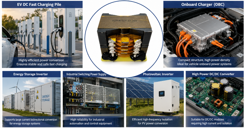
Application: DC Fast Charging Module, EV Onboard Charger, Energy Storage Inverter, Industrial Switching Power Supply, Photovoltaic Inverter

Main Functions
High-Power Energy Transfer
The large EE/ER magnetic core structure provides increased magnetic cross-sectional area, making the transformer suitable for power stages that must transfer substantial energy within each switching cycle.
High-Current Conversion Support
The winding window and layered coil arrangement provide additional design flexibility for circuits carrying relatively high current. Winding conductor selection can be adapted according to current density and thermal requirements.
Primary and Secondary Isolation
The multi-layer bobbin and winding arrangement provide space for reinforced insulation design between circuit sections, helping meet the electrical separation requirements found in charging and high-voltage power conversion equipment.
Thermal Management Support
The large exposed core surface and distributed winding structure allow heat generated during high-load operation to dissipate more effectively than tightly enclosed magnetic assemblies.
Stable PCB Installation
Wide terminal spacing, through-hole mounting, and larger solder pads help secure the transformer firmly to the circuit board, which is valuable in equipment exposed to vibration or repeated thermal cycling.
Power-Stage Voltage Transformation
The transformer can be designed around the voltage ratio required by AC/DC or DC/DC converter topologies, enabling efficient conversion between different voltage levels in high-power electronic systems.
Specific Application Scenarios
DC Fast Charging Power Modules
High-power charging piles require isolated AC/DC and DC/DC conversion stages capable of handling substantial energy flow. This transformer can be designed for charging modules where high current and stable continuous operation are major considerations.
EV Onboard Chargers
Onboard charger systems require compact but robust magnetic components capable of operating inside vehicle power electronics. The dual-core and reinforced PCB structure support high-density automotive power conversion applications.
Energy Storage Inverters
Battery energy storage systems often use bidirectional power converters that must operate under changing charge and discharge conditions. Large EE/ER transformers provide a suitable magnetic platform for these demanding conversion stages.
Industrial High-Power Switching Supplies
Industrial equipment, automated production systems, and control cabinets may require isolated high-power DC supplies. The transformer can be configured according to the voltage, current, and switching characteristics of the industrial power stage.
Photovoltaic Inverter Systems
Solar inverter power stages require reliable high-frequency magnetic components for conversion and electrical isolation. The high-power EE/ER structure is suitable for applications where the transformer must handle elevated current and sustained load.
High-Power DC/DC Conversion Equipment
The transformer can be integrated into DC/DC converters used in renewable energy, battery systems, and industrial power electronics where galvanic isolation and controlled voltage transformation are required.
FAQ
Q1: Why are EE55, EE65 and ER49 cores suitable for high-power transformers?
A1: These larger ferrite cores provide greater magnetic cross-sectional area and winding space than smaller high-frequency cores, making them better suited to higher power and current levels.
Q2: What is the advantage of a dual-core transformer structure?
A2: A dual-core structure increases the available magnetic path and effective core area, providing additional design margin for high-current operation and helping control magnetic flux density at demanding power levels.
Q3: Why is layered winding used in charging pile transformers?
A3: Layered winding allows primary and secondary sections to be arranged according to current, voltage ratio, coupling, and insulation requirements. It also gives designers more control over conductor placement and heat distribution.
Q4: Why does this transformer use wide PCB terminal spacing?
A4: Wider terminal spacing provides additional room for high-current connections and insulation clearances. Larger soldering areas can also improve mechanical retention on high-power PCB assemblies.
Q5: What information is needed when selecting a transformer for an EV charger?
A5: Important information includes converter topology, input and output voltage, rated power, switching frequency, maximum current, isolation requirement, allowable temperature rise, cooling conditions, PCB space, and target core size.
Q6: Can the same transformer design be used for both charging piles and energy storage inverters?
A6: Not necessarily. Although both applications may use high-power high-frequency transformers, winding ratio, current level, insulation arrangement, frequency, thermal conditions, and converter topology can differ significantly. The transformer should be designed around the actual power stage.





 Phone
Phone